Share this blog!

This post explains how to combine git commits by using git rebase and git squash.

Let's assume that we have a couple of commits as follows. --oneline gives the short version of git log output.

$ git log --oneline  
c123456 Edit file-B again  
b234567 Edit file-B  
a012345 Edit file-A

Quick tips: vim commands
  • :wq - to save and exit
  • i - to enter Insert mode
  • Esc - to enter Command mode from Insert mode
Google more on vim commands.

Let's assume we want to squash the edits to file-B together as one commit. By using git rebase, the history will be rewritten.

$ git rebase -i a012345  

The above command will open the editor with commit info up to the specified commit. Enter the Insert mode and edit the log as follows:

pick b234567 Edit file-B  
squash c123456 Edit file-B again 

Save and exit the editor and that's it! Check the commit logs again to ensure the results.

If you have already pushed your changes to a remote, you might need to force push your changes.

git push --force

That's it! Let me know if you encounter any problems or have any comments. Cheers!

Internship diaries #5

It’s the end of the internship experience and I feel lucky to have such a wonderful time at WSO2. I learned a lot on open-source technologies, middleware and their applications, ethics on JavaScript libraries, web services and most of all, problem solving, which had been contributing to the increase of my StackOverflow reputation as well.

As for extra-curricular activities, I learnt a lot about Table Tennis, Foosball and Carom and I even participated in the Tea-time championship as a part of Titans. The Secret Santa was one of the most exciting memories which include lunch outings and ice-cream outings.

As for the Data Mapper, the main work done during this phase was adding the format conversion functions.


Since the tree generation and the backend functionality was dealt with a JSON schema as the data, the data selected by the user had to be converted to JSON schema as well. The simplest was JSON to JSON schema, which was achieved by iterating over the keys and values in the JSON object to generate a matching JSON schema.

The CSV to schema conversion was achieved using an external library called mr-data-converter which converts CSV data to JSON which will be again converted to JSON schema by my previously written code.

XML and XSD conversion was the troublesome work since I was unable to find external opensource libraries with compatible licenses to use in the app. Most of the available libraries work with Node.js which again rules out the context of the app because the Data Mapper is supposed to be run in a static environment.

I achieved XML conversion using the HTML parsing functions and used its native methods to traverse through the XML. An interesting concept I came across during this conversion was the use of attributes in XML. And I had to come up with a key attributes to define the attributes in an XML content. For example,

<name id="345"> myName </name>

will be converted to:

name: {
        type: "string",
        attributes: {
                      id: {
                            type: "string"
                          }
                     }
      }

XSD conversion too had its own troubles with its namespaces and type definitions. XSD was a whole new topic for me and I learnt quite a lot about the tag names and their usages. During the conversion, I used a function where the first iteration would save the definitions and determine the root element, and a second iteration would traverse the root and build the schema.

Once the conversion was completed, I tested the functionality using SalesForce sample files which gave satisfactory results.

After taking the Data Mapper to a halt, I started looking into web services, especially RESTful web services. I was assigned with a task to develop a use case by incorporating a web service using JAX-RS and WSO2 products such as ESB, DSS and API manager. Currently I have worked around DSS to bind to a MySQL database, a web service to read information and I'm still working on connecting them using the ESB.

This internship experience has been such a wonderful time in my life. I learnt a lot on coding and working ethics, I improved my soft skills, especially on communication criteria, I got to meet some interesting people, share the knowledge as well as some good laughs. But all good things must come to an end. Only God knows what might be waiting for me in the coming new year, and I believe that the goodness will keep coming in. Thank you and Good Bye WSO2.


In a previous post, we discussed how to use a MySQL database in a data service using WSO2. The sample in this post will be updating the same data service, by adding a new query with a parameter and invoking it in REST style.


At a glance, the final output of the sample will be:


Add a new query

Let's add a new query to the last data service we created. In the Services list, when you click on a service, you will be directed to the service dashboard. The edit options are available under Specific Configuration. Let's edit using the wizard.


Click Next until the Queries are reached and add a new query with a parameter as follows. Note the ":fname" parameter in the SQL. After entering the SQL, click on Generate Input Mappings, which will automatically add input mappings.


Let's define an XML output as follows:


Click Save and Next. Let's skip the Operations and instead, add a Resource in the next page. 

Add a resource

This is where you will be mapping the path and parameters to the query we defined. In the Add resource dialog, define the desired path pattern and select the query, and the selection will automatically bind the parameter names.


Click Save and deploy the service. Try out the results using paths such as https://172.17.0.1:9448/services/PersonDataService/person/Sheldon. 


In this post, we created a REST service from patterns in Netbeans IDE and now we will be creating one manually using Jersey in Eclipse.

Create the project


I'm using Mars 2 distribution of Eclipse. To create the project, select New→Dynamic Web Project under Web. 


I'm using Apache Tomcat server v8.0. Click Next and set the build class location and click Next. Make sure to Generate web.xml and click Finish.


Add Jersey to the project


From this Jersey download site, download the bundle( I downloaded  Jersey JAX-RS 2.0 RI bundle ) which is a zip file containing the jars and dependencies. Copy all the jars (in api, ext and lib directories) into our project's WebContent/WEB-INF/lib directory. Refresh the project in Eclipse to make sure they are loaded.


Create the class


Now it's time to add the class to set the messages. Let's add a package named hello to src (Note: this value will be used in web.xml) and create a class in it as follows:


package hello;
import javax.ws.rs.GET;
import javax.ws.rs.Path;
import javax.ws.rs.Produces;
import javax.ws.rs.core.MediaType;

@Path("hello")
public class Hello {
    
    @GET
    @Produces(MediaType.TEXT_PLAIN)
    public String sayPlainTextHello() {
      return "Hello Jersey";
    }

}


Configure web.xml


Update the web.xml file as follows. This will register Jersey to handle requests.


<?xml version="1.0" encoding="UTF-8"?>
<web-app xmlns:xsi="http://www.w3.org/2001/XMLSchema-instance" xmlns="http://java.sun.com/xml/ns/javaee" xsi:schemaLocation="http://java.sun.com/xml/ns/javaee http://java.sun.com/xml/ns/javaee/web-app_3_0.xsd" id="WebApp_ID" version="3.0">
  <display-name>Hello World REST example</display-name>
 <servlet>
    <servlet-name>Jersey REST Service</servlet-name>
    <servlet-class>org.glassfish.jersey.servlet.ServletContainer</servlet-class>
    <init-param>
        <param-name>jersey.config.server.provider.packages</param-name>
        <param-value>hello</param-value>
    </init-param>
    <load-on-startup>1</load-on-startup>
  </servlet>
  <servlet-mapping>
    <servlet-name>Jersey REST Service</servlet-name>
    <url-pattern>/rest/*</url-pattern>
  </servlet-mapping>
</web-app>

Run the service


You can run the service by right clicking on the project and choosing Run as →Run on server to run the service. Go to http://localhost:8080/HelloWorldREST/rest/hello to view the results.


This post presents a sample data service created by WSO2's Data Services Server and incorporates a MySQL database.

Installing WSO2 DSS

You can follow the instructions on this document to install the server.

The database

I will be using MySQL as the source of the data. Therefore your machine must have MySQL installed in it. 

Quick tip: 

How to install MySQL in Ubuntu: use following commands.

$ sudo apt-get update
$ sudo apt-get install mysql-server
$ sudo mysql_secure_installation

To set up JDBC Driver: 

$ sudo apt-get install libmysql-java

and add ":/usr/share/java/mysql-connector-java.jar" to the PATH in etc/environment. Check related links for more information.


Additionally, you need to copy the mysql-connector-java-5.XX-bin.jar file into the /repository/components/lib/ directory.

I have created the following simple table(named person) in the database peopledb, which will be used in this sample.


Create the data service

Start the Data Services Server (In Linux, run command ./wso2server.sh in server_home/bin)


In the Main tab, under Services →Data Service, click Create. Specify a name and click Next.


Add new data source

Specify a name for the data source and set the parameters to point to the MySQL database.
Save and click Next.

Create a query

Just like its name stands for, the queries retrieve/write data. The following settings define a query to get all the entries of the table. This section introduces another query and an operation that uses a different sql query


The output is set as xml and People and Person are set as group and row so as to get an output in the form of:
<people>
    <person>
        ....info
    </person>
</people>

To map the output of the query to the xml tags, an output mapping must be defined. Click on Add New Output Mapping and set the mappings as follows.


Save and click Next.

Add operation to query

An operation can bind a query to the server. Simply define a name to the operation and set the query.
Click Finish and you will be redirected to the services page with your new service up and running.

Deploy the service

The new service will be running if the defined settings were correct. Clicking on the service will open the statistics of it.


As the Endpoints, it will show the URL of the service we just created. To use the operation we defined (getPeople) simply go the URL:-
http://172.17.0.1:9763/services/PersonDataService/getPeople

Multiple queries and operations

The following is another query added to the same data service to get information on one entry. Add a new query as follows:
I have used JSON as the output format. And bind an operation to it as follows. 

Here is another query - an insert query to add Barry to the table.

Related links


In this post, we went through a simple hello world application in JAX-RS and now we're going to widen our circle a wee bit to add some calculations and read @PathParam's.


1. Create a web application


Just like the last time, create a new project, choose Java Web and Web Application from the list, select a server (I chose Glass Fish) and create the project. 

2. Add the logic 


Now let's add a class that will be responsible for calculating the rates when the currencies are passed as parameters. For this, I used a package named exchangerate in which I created the CurrencyCalculator class with the following code.


public class CurrencyCalculator {

    private HashMap<String, Double> rates;

    public CurrencyCalculator() {
        this.rates = new HashMap();
        this.rates.put("USD", 1.0); //using USD as the base
        this.rates.put("EUR", 0.933);
        this.rates.put("LKR", 149.132);
        this.rates.put("AUD", 1.345);
        this.rates.put("YEN", 114.123);
    }

    public double getExchangeRate(String from, String to) {
        if (rates.containsKey(from) && rates.containsKey(to)) {
            double toVal = rates.get(to);
            double fromVal = rates.get(from);
            double rate = toVal / fromVal;
            return rate;
        }
        return 0;
    }
}

3. Add the REST service

Now it's time to write the service that will connect the user to the above logic. Just like the last time, right click on the project, select New→RESTful Web Services from Patterns. Select Simple Root Resource define the path and MIME type. 


4. Add PathParams to the service

Our goal is to match a URL like rates/USD/LKR to the above class's getExchangeRate("USD", "LKR")

rates/USD/LKR  →  getExchangeRate(USD,LKR);

For this we will have to use @PathParam annotations.

The following format is used to decode the path as a parameter to a method.

@Path("myPath")
public class ClassName {

    @GET
    @Path("{name}")
    @Produces(MediaType.TEXT_PLAIN)

    public String methodName(@PathParam("name") String name) {
        return "passed value: " + name;
    }

}

The result of the above would be:

myPath/sachithra  →  "passed value: sachithra"


5. Bind logic and path 

Using the above format, let's use an instance of the CurrencyCalculator and bind a path with 2 segments to a method with 2 parameters. 

@Path("rates")
public class ExchangeRate {

    private final CurrencyCalculator rates;

    public ExchangeRate() {
        rates = new CurrencyCalculator();
    }

    @GET
    @Path("{from}/{to}")
    @Produces(MediaType.TEXT_PLAIN)
    public String getRates(@PathParam("from") String from, @PathParam("to") String to) {
        double value = rates.getExchangeRate(from, to);
        String resultText = "";
        if (value != 0) {
            resultText = "1 " + from + " is eqdual to " + value + " " + to;
        } else {
            resultText = "Sorry, the currencies you defined are invalid or not yet implemented.";
        }
        return resultText;
    }

}

6. Run the service

Deploy and run the project and try out the results by using paths (eg: http://localhost:8080/ExchangeRate/webresources/rates/USD/LKR).


The complete implementation of the two classes can be found on this gist.

This post explains steps to create, deploy and run a simple Hello world application in JAX-RS (in Netbeans).

Update: Check this article to add Jersey manually.


1. Create a web application

In Netbeans IDE create a new web project by File→New Project. Select Java Web in categories and choose Web Application in Projects.

Define a project name and set GlassFishServer as the server. If it is not installed, you may have to install it - simply choose Add and install it on the go. Once the project is created, the index file will be opened in the Source pane.

2. Add the Root Resource Class

You can refer this article from Oracle Docs for more information on Root Resource Class and the annotations. 

The easiest way to add the Root Resource Class is to use the pre-designed template from Netbeans. For this, right click on the project clicke New→RESTful Web Services from Patterns. 

Select Simple Root Resource and define the resource package name, path, class name and MIME.


Once finished, the HelloWorld.java will be added and appeared in the Source pane.

In the newly created class, find the getHTML method and return a valid HTML message.

public String getHtml() {
        return "<html lang=\"en\"><body><h1>Hello, World!!</body></h1></html>";
}

What did we just do?


@Path("helloworld")
public class HelloWorld {

    @GET
    @Produces(MediaType.TEXT_HTML)
    public String getHtml() {
        return "<html lang=\"en\"><body><h1>Hello, World!!</h1></body></html>";
    }

}

Just before the class definition, there is an annotation @Path("helloworld") which binds the relative URI webresources/helloworld into the HelloWorld class. The webresources/ path was actually set by the template, which is defined by @javax.ws.rs.ApplicationPath in the ApplicationConfig class in the package. 

The @GET is similar to the HTTP GET method and the method following the GET annotation represents the method to be executed.

The @Produces defines the output format, which in our case was set to TEXT_HTML, which is why we are returning an html output.

Refer this article for more info on annotations.


3. Test the web service

Right click on the project and click Test RESTful Web Services. If it prompts for configuration, go for the defaults set by the dialog box and click OK.

The test will deploy the application and initialize a test client in your browser. Click on helloworld resource on the left and click Test on the appearing pane to test the resource.


4. Run the service

When running the application, it will show only the contents of the index file regardless of the service. The service can be accessed by the path defined in the Test client (in the above test client it is http://localhost:8080/HelloWorldREST/webresources/helloworld).

You can add the path to the index file as in:

<a href="webresources/helloworld">Go to hello world</a>

Or it could be set as the default in run configuration on the project properties. Right click on project and click Properties→Run and define the Relative URL (for the above, it would be webresources/helloworld).


This post contains a general explanation on web services and related topics. You can refer related links for detailed guides on this topic.

What is SOA?


A service - a repeatable business task (eg: get exchange rate)
Service orientation - how a business is integrated as services
Service oriented architecture (SOA) - an IT architectural style that provides service orientation

A web service is an implementation scenario of SOA, which is encompassed by SaaS or Software as a Service.

What is a web service?


Simply put, a web service is a piece of software focusing on a specific task, designed to be used through a set of methods and parameters.

For example, imagine you are creating an app that has the requirement to get the conversion rate between Sri Lankan Rupee and USD. You can go for the tiring method of saving your own information in a database and write code to get the data. Or you can use a web service (say developed by company-A) that does that specific task for you, where you have to use a method (say getExchangeRate) to get required information. Sometimes, you will have to pass certain parameters too (like the type of currencies, LKR and USD).

(Update: this post presents a sample RESTful exchangerate service.)

The beauty of a web service is encapsulation. In the above scenario, you did not have to worry about how the data was stored or calculated.

With that in mind, let’s take a look at the definition of web services again.

Web services is a technology for transmitting data over the internet and allow programmatic access to data through standard internet protocols.

Who provides and uses web services?


In the above scenario, you were the service requester and company-A is the service provider. There has to be a service broker who will handle the directory and support the registration of services.

The language used to exchange data is XML and the communication is provided by SOAP (Simple Object Access Protocol). The services are described using WSDL (Web Services Description Language) and they are listed and searched for with the help of UDDI (Universal Discovery Description and Integration).


Related links

During the implementation of delete and clear container operations, I had to implement delete confirmation dialog boxes using Bootstrap Dialog. I thought of using a common confirmation function, which would take the action function as a parameter and call it if confirmed. (Note: jQuery's confirm provides similar functionality with the default dialog box)

I started by defining the following approach which works fine with global functions. But when Backbone view instances are concerned, it did not work. I assumed the problem was that the passed function has incorrect context - note that "this" prints different objects in the console.

var viewDemo = Backbone.View.extend({
    mainFunc: function(){
        this.intermediateFunc(this.ABC);
    }
    intermediateFunc : function(callback){
        console.log(this); //prints the correct view
        callback();
    }
    ABC : function(){
        console.log(this); //prints 'window' when passed through a function
    }
});


As usual, StackOverflow came up with the solution when I asked this question. The solution of mu is too short explains 3 approaches:

1. Using Function.prototype.bind


mainFunc: function(){
    this.intermediateFunc(this.ABC.bind(this));
}

2. Function.prototype.call or Function.prototype.apply


mainFunc: function(){
    this.intermediateFunc(this.ABC, this);
},
intermediateFunc : function(callback, context) {
    console.log(this); //prints the correct view
    if(context)
        callback.call(context);
    else
        callback();
}

Or the same could be used as:

mainFunc: function(){
    this.intermediateFunc(this.ABC, this);
},
intermediateFunc : function(callback, context) {
    console.log(this); //prints the correct view
    context = context || this;
    callback.call(context);
}

3. The old var self = this; trick


mainFunc: function() {
    var _this = this;
    this.intermediateFunc(function() { return _this.ABC() });
}

Internship diaries #4


At the start of the 4th four-week period, a review meeting was held where several new tasks were specified. I started working on them starting from the minor tasks.

The connector make over

One such task was converting the connectors from straight lines to lines with margin-like ends.
Earlier, the connector was simply an svg:line where I update the x1, y1, x2 and y2 properties directly using d3.selector.attr. In the new requirement, an svg:polyline was introduced as the solution where the points had to be updated instead of the previous x and y coordinates. Each polyline was of 3 segments and needed 4 pairs of coordinates. The earlier connectors already had 2 pairs of coordinates and I used the following to calculate the remaining 2 pairs.


In order to improve clicking on the connector, I added another polyline with the same points but higher width and invisible in the editor except for mouse hover. The events regarding the connectors were set to be captured by this underlying polyline and the increased area improved the usability of the connectors.
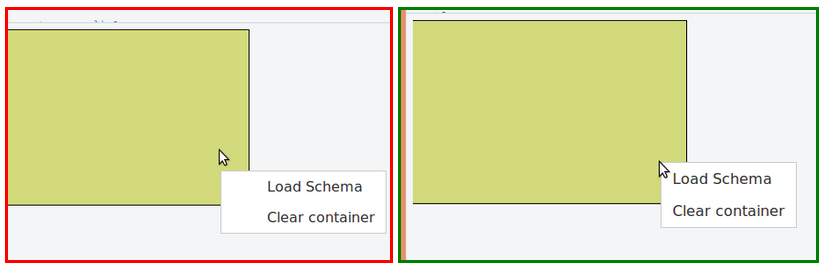
Clicked right

Another task was to add the load-file and clear containers functions to a right click menu on the container. For this I used predefined menus in <ul> tags in the main file, which were toggled on contextmenu event. There was a problem causing the menus to be displayed off the desired positions. After researching on this I found out the cause and the solution.

Lists (both unordered and ordered) have padding and margin set by default which was causing the undesired shifts. The default padding was meant for the bullet icons or numbering of list items. The simple solution was to set padding and margin to zero in the <ul> of the menu.

Hidden foreigner

Another problem faced during right click menu implementation was that the menus were not working for upper nodes of the container. After testing on multiple scenarios I found out that this occurs in Firefox but not Chrome and that the inspect-element pointed to a blank square rather than the nodes. The research on this showed that the <foreignObject> I used to hide the file-input was literally covering the upper nodes. Although I have set display:none to the input, I had not hid the <foreignObject> itself which was 100px wide and tall. To solve it, I set display:none to the parent element and as an extra precaution, set the height and width to 1px.

Build on the go

Among the major tasks I completed were dynamic addition of the nodes to the tree, which was also a use case of allowing the user to build a schema manually. I started on it by adding the root element. I used BootstrapDialog to create dynamic modal dialog boxes that gets the information such as the title and the type of the node. When the root element is added, a schema is initiated and stored in the Tree object.

The rules assumed as optimum are as follows:

  1. The options for the type of the root element are limited to Object and Array
  2. Only nodes of type Object or Array are allowed to add child nodes
  3. New nodes to the root element are added only as children nodes
  4. Sibling added to a node will be placed right after the triggered node
  5. Child added to a node will be placed as the last child of the triggered node

When I was working on updating the schema during node addition, I noticed that JS does not allow adding new nodes to a specific location (to be added as the immediate sibling) since “JavaScript objects are unordered lists of properties”. Therefore a custom method was to be used to set out the right order.

I created a new temporary object, looped through the keys of the parent and kept adding them to the new object. When the triggered node is detected, I added the new sibling node and kept adding the rest of the nodes and finally replace the parent object with the new object.

Once the schema update was completed, I worked on displaying the new nodes. I wrote two (for sibling and child use cases) recursive functions to detect the node right-above the desired location. The functions were based on the HTML DOM hierarchy of the browser. Then I pushed down the nodes below the desired location and added the new node.

One of the problems I faced was that, the new nodes were added at the end of the HTML DOM hierarchy regardless of the position of the node in the tree, which gave incorrect results. Therefore a mechanism was used to re-order the elements in par with the schema, which was implemented using jQuery’s append and detach.

It’s the end of the 16th week of the internship and this post explains the progress of the JavaScript based data mapper so far.

After the ‘backbone’ of the app was set out, focus was given to adding more UI functionalities – where the user can customize the input, output and the operations.


The front-end

So far, the data mapper initializes with an input container, output container and a tool palette(integrated from the NEL tooling platform).

Each tool in the tool palette can be dragged and dropped on the canvas, where the corresponding operator is drawn. Each operator has its defined set of input/output labels and valid types and each operator has the option to be deleted.


Additionally, the direct connectors (Connecting Input container to output container) will be corresponding to a “Direct operator” without visible components.

The “Input” tool in the “Tree containers” is used to drag and drop extra input tree containers.

Each tree container has a total of 3 options which may appear or not based on the content in it. Empty containers have the option “Add new root” in place of the “Clear container” option in non-empty containers and the abstract functionalities of the options are as follows:


  1. Load schema: Select the structure based on a file of one of the types of XML, JSON, CSV, XSD, JSON Schema.
  2. Add new root: Build the structure manually by defining the root and adding nodes.
  3. Clear container: Empties the container


The extra containers added by the user have the additional option to be deleted.

When reading from a file or building the structure in a tree container, the containers create “Node”s in a tree-structure. The parent nodes are of type Object or Array and others are leaf nodes and each leaf node has an “Anchor”. Input type anchors can be dragged and dropped on a node of opposite type which will create “Connector”s. A hidden svg:polyline of higher width is used to improve clicking on the connector.

Each node has 3 options as follows:

  1. Add node: Add a new node to the structure.
  2. Edit node: Edit the title and type of node
  3. Delete node: Delete the node from the app.

When adding a new node, it is added as a sibling by default, but if the triggered node is a parent node, there is an option to add the new node as a child. When adding a child node, the child is added as the last child of the triggered node and when adding a sibling node, the sibling is added as the immediate next sibling of the triggered node.

The back-end at a glance


The tree structure of each tree container is maintained as a JSON Schema. When reading a file of a different type such as XML, JSON, CSV and XSD, the structure is converted to JSON Schema type and is manipulated throughout the app.

As a whole, the app creates and maintains a global JS object “Diagram” which includes the objects of the diagram as Backbone models or collections.


1
2
3
4
5
6
7
8
9
var Diagram = {
    Canvas: {}, //the editor = svg
    TreeContainers: {}, /* Backbone collection corresponding to Input/Output container
                                 the model contains the loaded schema as a JS object and a collection of nodes */
    Connectors: {}, //all the 'lines' drawn in the application
    ToolList: {}, //The collection of tools
    PalleteView: {},
    Operators: {} //a Backbone collection of all the operators in the canvas
 };

The result

The generated graph of mappings is calculated by means of the input/output adjacency lists of each operator. The result includes:
  1. A variable list: All the nodes
  2. Operators: A list of all operators including direct operators
  3. Input adjacency list: Input nodes of the operators in the list
  4. Output adjacency list: Output nodes of the operators in the list


One of the tricky requirements faced during connector implementation was the right-click menus. I used a shared html ul components which were triggered by assigning classes, since it would be less-consumptive than creating menus for each component.

The connectors of the data mapper are used to connect input nodes to output nodes and they are implemented using svg polylines. The stroke-width of the lines were maintained at 2 and this made it hard to click on them. Therefore it was suggested to use a hidden background overlay that would be highlighted during mouse over and click and the right click menu was to be triggered on this overlay.

 As for the overlay, I used a copy of the connector, but with a wider stroke-width and defined mouseover and mouseleave event functions to change the opacity of the overlay.

It worked fine until it was observed that, when the mouse is hovered on the right click menu, mouseleave is triggered and the highlight is removed. I wished to keep the connector highlighted during its focus, which includes right click menu propagation.

After discussing with a team member on multiple solutions, it was decided to use a simple solution of manipulating classes to check if menu is displayed before triggering mouseleave.

The following needs improvement, but demonstrates the basic idea of the solution:

  1. Corresponding question on StackOverflow


As a requirement in my internship project (as described in this post), I had to insert new attributes to the JSON schema to a specified location, ie, to add an immediate sibling to the clicked node. Since JavaScript is an unordered list of properties, typical JSON methods could not be used. Therefore a solution where iterating over the keys and cloning them to a new object was used.

The sample code is as follows: 
The highlight of this week's implementation was updating the schema with the user input. The user is basically allowed to add nodes to a schema and that logic could be used to build a schema from scratch which needs an additional step of setting the root element.

The modal dialogs were implemented using BootstrapDialog which offered simple a simple template to create dynamic modal dialog boxes. I used a simple String operation to hide the add-as-child option.

var isLeaf = this.isLeafElement ? ' style="display:none;" ' : ' ';
BootstrapDialog.show({
    title: "Add new node",
    message: 'Title: <input id="title" type="text"><br>Type:<select id="type">' + this.getTypeOptionList("Object") + '</select><div ' + isLeaf + ' ><br>Add as child: <input type="checkbox" id="isChild" ></div> ',
    draggable: true,
    buttons: [{
        label: 'Add',
        cssClass: "btn-primary",
        action: function (dialogRef) {
            self.model.addNode(dialogRef.getModalBody().find('#title').val());
            dialogRef.close();
        }
    },
        {
            label: 'Cancel',
            action: function (dialogRef) {
                dialogRef.close();
            }
        }
    ]
});


The rules I assumed as optimum included:

  1. The options for the type of the root element are limited to Object and Array
  2. Only nodes of type Object or Array are allowed to add child nodes
  3. New nodes to the root element are added only as children nodes
  4. Sibling added to a node will be placed right after the triggered node
  5. Child added to a node will be placed as the last child of the triggered node
The initial goal was to update the schema, and to reload the container which will draw the tree-structure according to the updated schema. However, this will remove any current connectors attached to the container. Therefore dynamic node drawing was needed - which was kept for later consideration.

The schema-update was achieved using a recursive method, which was quite similar to the method I used to get the JSON path from a schema.

Initially, it would determine the relevant parent node of the expected new node and iterate the schema to find it. Adding as a child was not a big deal since it was to be added as the last child of the parent and simply updating the object as data[newAttribute] = newValue; would give the desired result.

Adding the sibling was the tough job since, it had to be added as the immediate sibling - to enhance user experience. The main reason was that JavaScript objects are unordered lists of properties. Therefore, in order to achieve the desired result of adding as the immediate sibling, I had to follow a String operation on parent data of the node.

The steps taken were:

  1. Select the parent data set - the target
  2. Detect the triggered node in the target set as a String
  3. Concatenate the triggered node string with the new node string
  4. Replace with the previously detected string
  5. Parse the new string as a JSON 
UPDATE: The string operation was replaced by an iterating function as in this post.

I was implementing the right-click menus for the nodes in the tree-container, when I noticed that they act weird in Firefox. I cross checked against Chrome and it was fine. When I tried to inspect-element in the browser, it pointed to a foreignObject, a piece of html where I hid the input trigger.

Fig 1

Each container was set to have an html input of type, file that would be triggered during file loading. The file loading was meant to be from a right-click option (Fig. 1), therefore, had to be hidden, and I needed it to be related to the specific container.


At the time of the implementation, the quickest solution was to append it to the container svg group while display:none-ing. So I simply appended a foreignObject with the input option to each tree-container. The mistake I made was assuming that the browser would not see the display-none elements.

var fo = parent.append("foreignObject").attr("x", 0).attr("y", 0).attr("height", 100).attr("width", 100);
var input = fo.append("xhtml:input")
            .attr("type", "file")
            .classed("schema-select", true)
            .attr("name", "input-select[]")
            .attr("id", this.id + "-schema-select")
            .attr("accept", "application/json")
            .style("display", "none")
            .on("change", function () {
                self.fileChange();
            });

The troubles started long after that, when I was implementing the right click menus for each node. The menus worked fine with the nodes positioned lower, but did not work or partially worked with the upper nodes.


With the help of a member of the UX/UI team, the cause was found - the foreignObject. I had used display none only on the input and set considerably large dimensions, which practically covered the nodes, completely or partially.

Since, Firefox and Chrome treat the elements differently, the visibility was different.

The solution was to set display:none to the foreignObject. As precautions, I also made use of the z-index and reduced the dimensions of the foreignObject.


One of the tasks from this week’s review meeting was to improve the interface of the connector from a simple line to a line with margins in order to make it more visible even with harsh angles.

Basically, I had to convert this,
to this.


Earlier, the connector was simply an svg line where I update the x1, y1, x2 and y2 properties directly using d3.selector.attr. In the new requirement, an svg polyline was the solution where the points had to be updated instead of the previous x and y coordinates.

A polyline with 3 segments needs 4 pairs of coordinates. I already had 2 from the line and a simple calculation was used to derive the remaining 2 pairs of coordinates.
My approach was to use svg line during anchor-drag and replace the line with polyline during anchor-drop.

With this approach, the next problem was updating the connector positions during container drag. In order to solve it, I introduced position values(x1, x2, y1, y2) to the "Connector" model and a method "setPoints" which will set the "points" of the polyline using the values and the above calculation.

And the problem was solved by replacing the previous method that updated the line's x2, y2 attributes, by the new setPoints method.

I am working on the Data Mapper tooling and came across the requirement to create custom right click menu for my container box, which was a rectangle in svg.

The result obtained after googling was quite satisfactory but there was some CSS problem. The loaded menu was slightly off the desired position, that is the block was about 20px below the desired position and the list elements were off to right.

After spending some time on StackOverflow, I found the cause of the problem and the solution. It was all in default CSS.

Lists (both unordered and ordered) have padding and margin set by default which was causing the undesired shifts. The default padding was meant for the bullet icons or numbering of list items. The simple solution was to set padding and margin to zero in the <ul> of the menu.

The complete solution is as follows:
The Information Security Quiz 2016 was held on 11th of October successfully with the participation of 23 teams from 10 universities/Institutes in Sri Lanka. I participated in it as a member of the team Phoenix representing University of Moratuwa.


The programme started off with a brief talk by the organizing committee and then the quiz started. The quiz comprised of 8 rounds, with each round focused on a particular domain as follows:
1. Basic security concepts 
2. Cloud security and Privacy 
3. Security Tools 
4. General Network Security Technologies 
5. Physical and environmental Security 
6. Cryptography 
7. Laws and Standards related to Computer Security 
8. Software Development and Security

Our team was able to win the first round on Basic Security Concepts and another team from our university was able to win the entire quiz!


Next PostNewer Posts Previous PostOlder Posts Home